Design Guidelines for Plastic Parts
1. Introduction
1.1 What are Plastics?
- Plastic materials contain a mixture of molecules
- The major portion is made up of large molecules known as polymers
- Remainder is composed of much smaller, widely differing types of molecules which are collectively referred to as additives
- Polymers are long chain molecules formed due to the reacting together or polymerisation of different organic materials called monomers
- Their composition always includes atoms of carbon, joined together, by primary covalent (electron sharing) bonds, to other atoms like hydrogen, oxygen, nitrogen, fluorine, silicon, sulphur, chlorine, etc
1.2 Sources of Plastics
- Sources of plastics are coal, petroleum & natural gas. Calcium carbide, ethylene, propane, benzene etc. are starting chemicals for producing synthetic resins
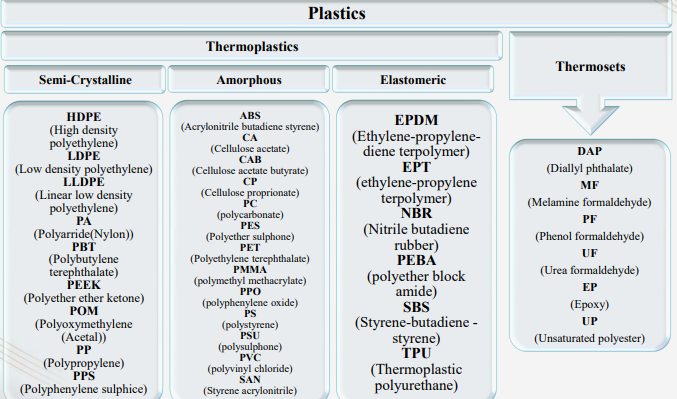
2. Types of Plastics
3. Material Selection
What are the key caused of plastic product failure?
Plastic product failure occurs almost 60% due to wrong material selection. Below image shows main causes of plastic product failure, from which proper material selection playes a vital role.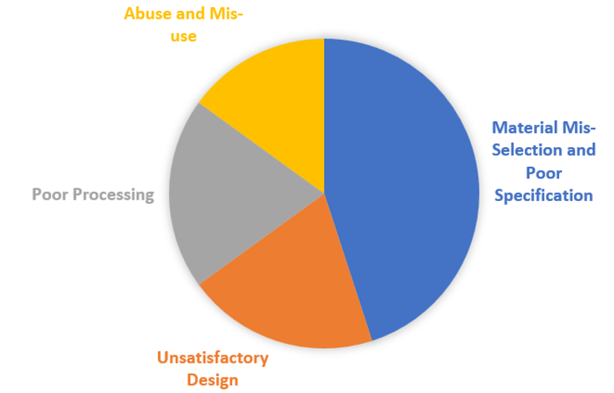
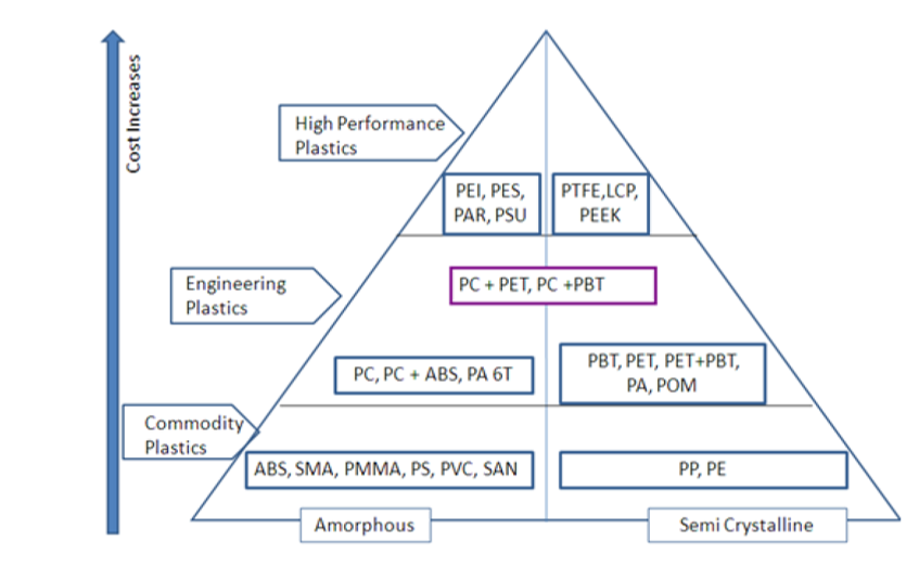
Pyrmid diagram shows Material classification with respect to properties.
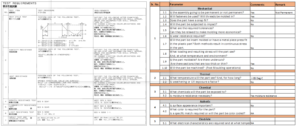
- Obtaining the application requirements is the first step in choosing the right material for the product. These specifics are supplied by the client in a document known as the SOP (Statement Of Purpose). This document helps us understand the ranges of the material properties.
- Primary Screening Procedure for material selection.
- Secondary Screening Procedure for material selection.
Material Selection Procedure
Below is the example of primary screening SOP document
Below is the example of secondary screening betwwen PC & PMMA material
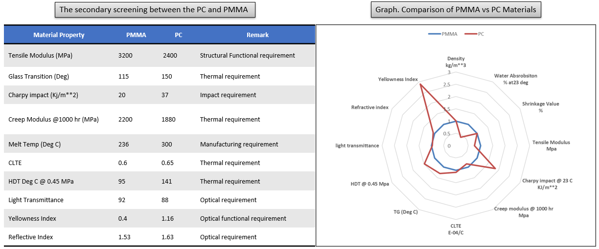
The detailed analysis on material shows that PC shows better Thermal properties, Impact properties, Glass Transition temperature properties as compare with PMMA, where as PMMA has advantage for structural stiffness, Long term creep modulus, CLTE and in optical properties.
3.1 Material Properties
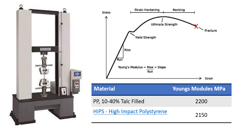
- The ratio of induced stress vs strain is young's modulus. This is material property to resist deformation
Youngs Modulus
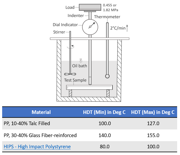
- The heat deflection temperature or heat distortion temperature (HDT, HDTUL, or DTUL) is the temperature at which a polymer or plastic sample deforms under a specified load. This property of a given plastic material is applied in many aspects of product design, engineering and manufacture of products using thermoplastic components
Heat Distortion Temperature (HDT)
4. Plastic Product Design
-
Important aspects to be considered while designing a plastic part are
- Wall Thickness
- Coring Out
- Draft
- Material Selection
- Parting Line
- Undercuts
- Aesthetic Surface Finishing
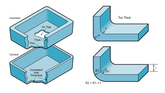
4.1 Design Criteria: Wall Thickness
- Wall thickness depends on shape, function and material used
- General range from 2 mm to 4 mm. Thin wall (injection molding ) ~ 0.5 mm
- Thinner wall cools faster, hence short cycle times => lowest part costs
- Avoids warpage and build-up of stress
- Easier to fill in the mold cavity
- Any transitions should be uniform
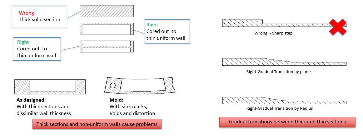
- Keep wall thickness as uniform as possible
- Use gradual transitions between thick and thin sections
- Wall thickness must suit both function and process
- Wall thickness guide range is:
- 0.75 mm to 3 mm for reinforced materials
- 0.5 mm to 5 mm for unreinforced materials
- The transition should be very gradual. Local thickening is permissible up to 0.5 mm transitioned over a minimum of 30 mm in all directions.
Example of Wall Thickness
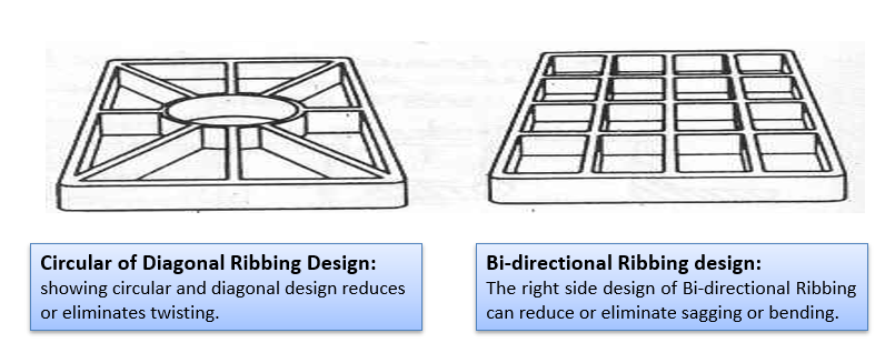
4.2 Design Criteria: Ribs/Gussets
Ribs provide a means to economically augment stiffness and strength in molded parts without increasing overall wall thickness. Other uses for ribs include: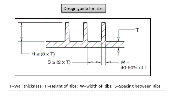
Rib Design Guidelines
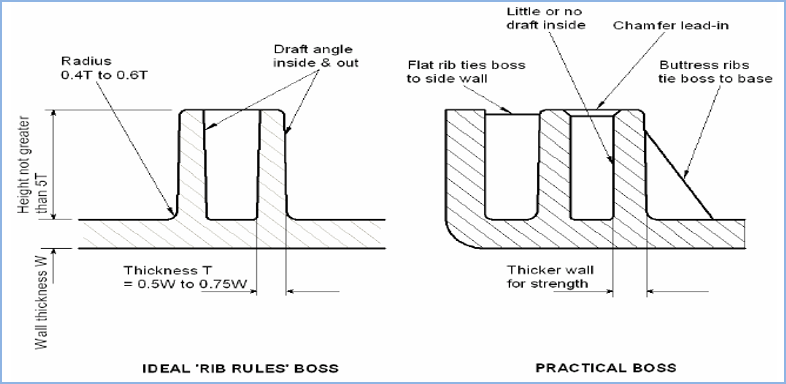
4.3 Functional Design (Bosses)
Bosses Design Guidelines
4.4 Weak Steel condition
Sharp or weak steel usually where you have very long and thin pieces of steel in the tooling usually between ribs are too close to each other or they meet the outer from at the tight angle leaving a point in the core tooling.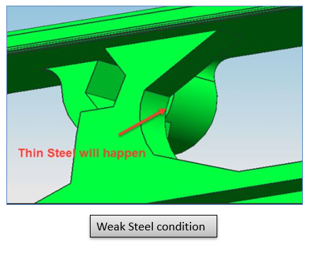
4.5 Manufacturing Design (Parting line)

4.5 Manufacturing Design (Sharp Corners, Undercuts)
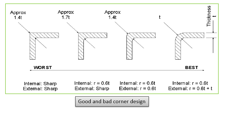
CORNERS
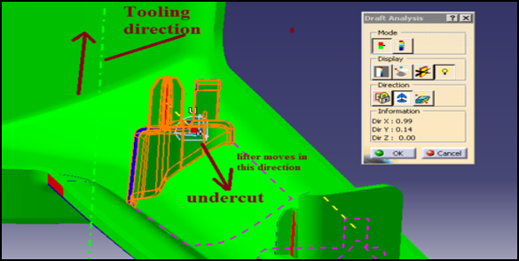
UNDERCUTS

4.6 Manufacturing Design (Drafts)

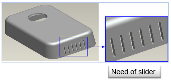
4.7 Manufacturing Design (Slider -Lifter)
Slider
Lifter
4.8 Aesthetic Design (Texturing)
Improving Mold ability
- Adding texture to a core can help to hold the part on to the core without manual undercuts which could create sink marks
- Texture applied on the core side and across lifters and/or slides, for some materials, can hide the shadow marks which sometimes will show through from the front of the part when the Class"A"side is polished
- Texture is sometimes applied in order to better hold paint during as secondary molding operation
- Texture applied in the correct design and location can help to minimize turbulence created by plastic flow Texture can provide a functional rough surface finish, on a roll, for example to help the roll stock through the rolling process
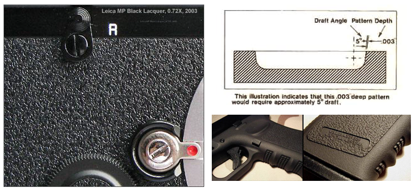
Texture depth and side wall draft considerations
To assure clean ejection of part,1.5 – 2ºof draft per .025 mm texture depth is given Texture depth can be reduced in specific areas and/or the texture pattern can be softened on surfaces where there are ejection concerns4.9 Aesthetic Design(Sink Mark)
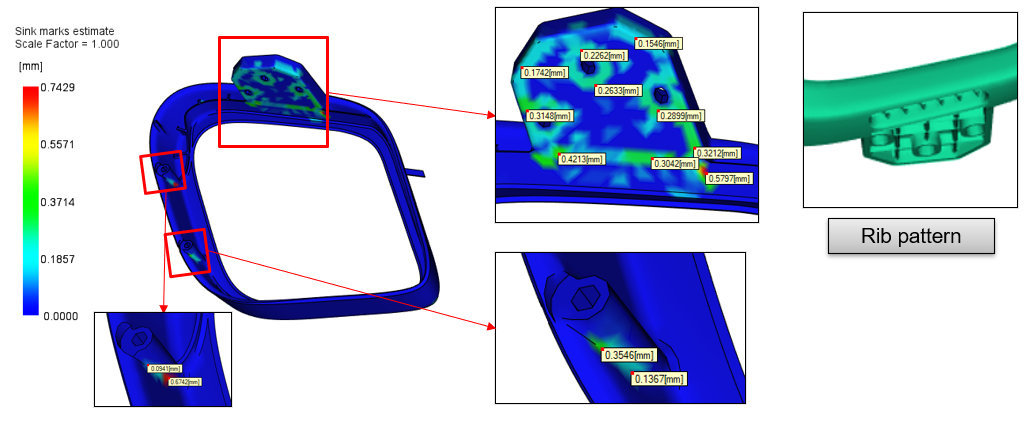
- Sink marks appear as depressions on the surface of a molded part
- These depressions are typically very small; however they are often quite visible, because they reflect light in different directions
- The visibility of sink marks is a function of the color of the part as well as its surface texture so depth is only one criterion
- Although sink marks do not affect part strength or function, they are perceived to be severe quality defects
- Localized geometric features: Sink marks typically occur in moldings with thicker sections, or at locations opposite from ribs, bosses or internal fillets
Remedies:
- Change the part geometry, part design to minimize thick sections and reduce the thickness of any features that intersect with the main surface.
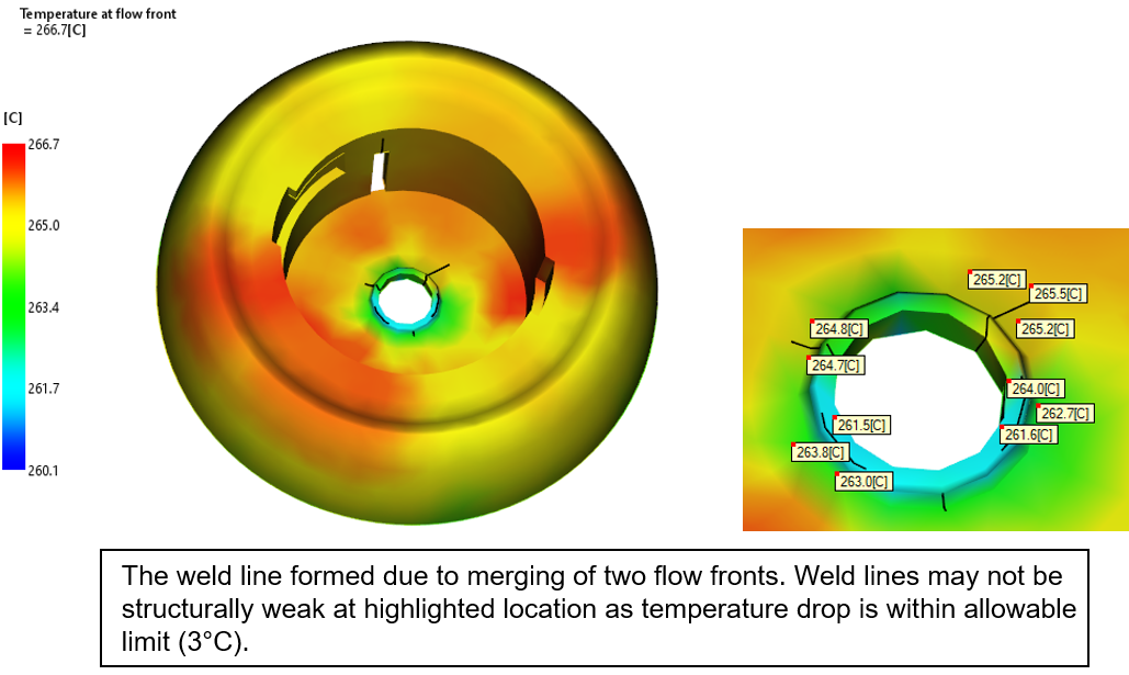
5.0 Weld lines
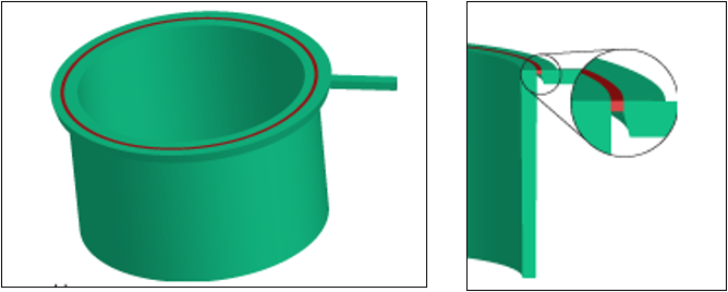
Weld lines refer to the lines that occur on a plastic product surface when the cold slug melts. In areas of mold cavity where the molten plastic meets inserts or holes, areas with inconsistent flow speed/flow interruptions, where multiple flows meet or when jetting happens during mold filling, linear weld marks tend to occur due to imperfect bonding.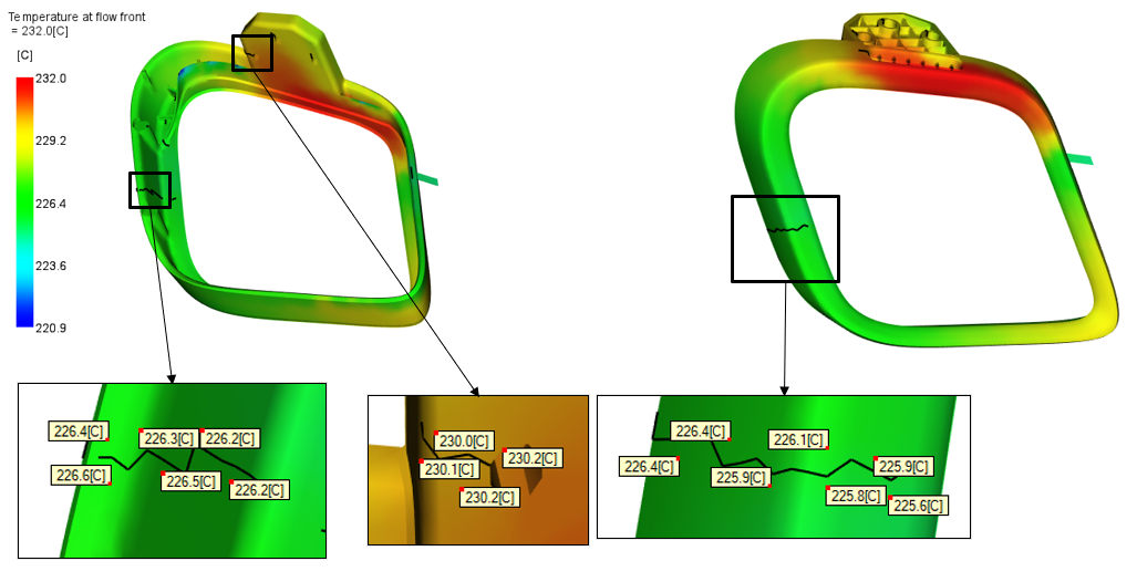
- The weld line formed due to merging of two flow fronts. Weld lines may not be structurally weak at highlighted location as temperature drop is within allowable limit(3°C)
5.1 Manufacturing Design (Warpage)
Warpage
Can be defined as a dimensional distortion in a molded product after it is ejected from the mold at the end of the injection
molding process. All polymers shrink during cooling. However, if a part shrinks to different degrees in different places,
it can warp.
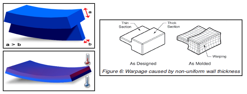
Contributors to Warpage
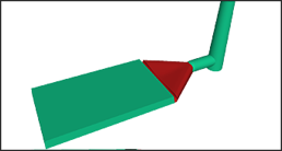
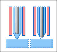
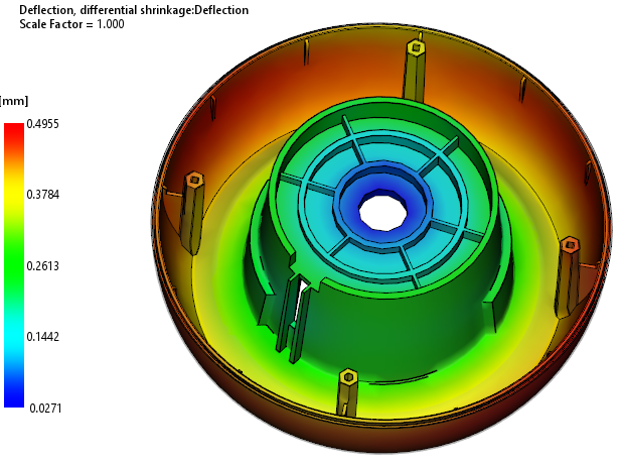
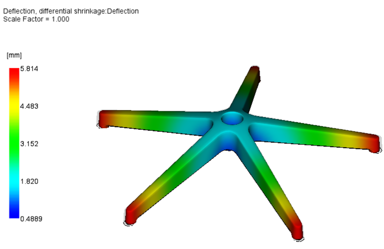
- Differential Shrinkage: This type of shrinkage is often caused by variation in crystalline content and volumetric shrinkage. The following figure shows a thin rib attached to a thick top. In general, the cooling rate of the top will be lower than that of the thin section. The top will have increased crystalline content and therefore, will shrink more and cause the warpage
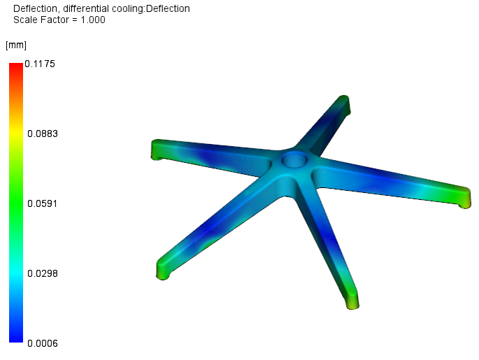
- Differential Cooling: Shrinkage due to differential temperature typically results in bowing of the component, as shown in the figure. Usually this type of shrinkage is due to poor cooling system design. While the part is in the mold, temperature differences from one side of the mold to the other cause variations in shrinkage through the thickness of the component. In addition to this, any temperature differences at ejection will cause further warpage as both sides of the part
- The dynamic of thin and thick sections and their cooling times creates warping as well. As would be expected, as a thick section cools it shrinks, and the material for the shrinkage comes from the unsolidified areas causing the part to warp
- Other causes for warping might include the molding process conditions, injection pressures, cooling rates, packing problems, and mold temperatures. Resin manufacturers’ process guidelines should be followed for best results.
5.2 Assembly Design
Types of Joining plastic
- Ultrasonic Welding, Staking, Spot welding & Inserts
- Hotplate welding
- Vibration welding
- Self tapping screws
- Threaded metal inserts
- Fasteners
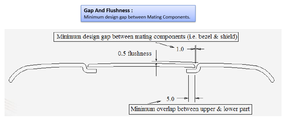
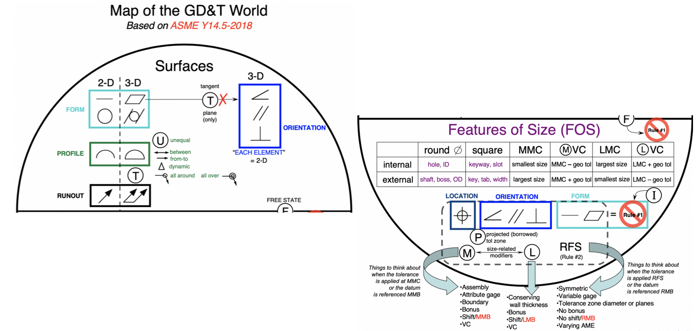
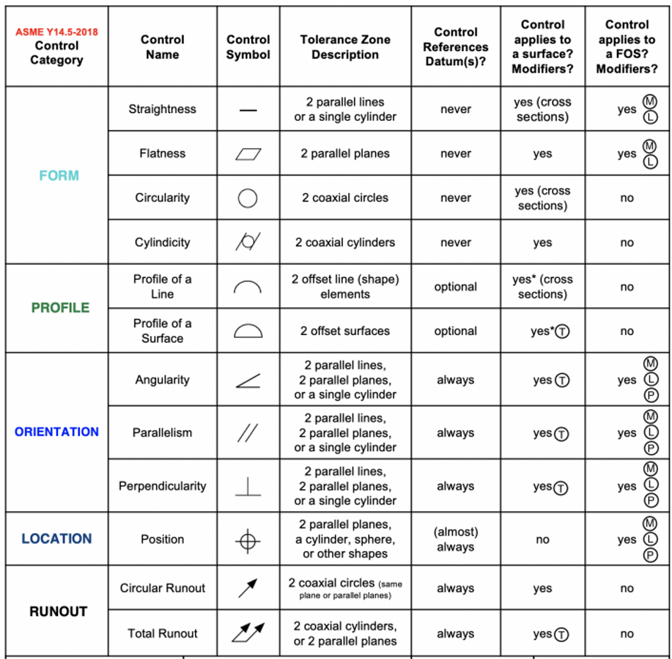
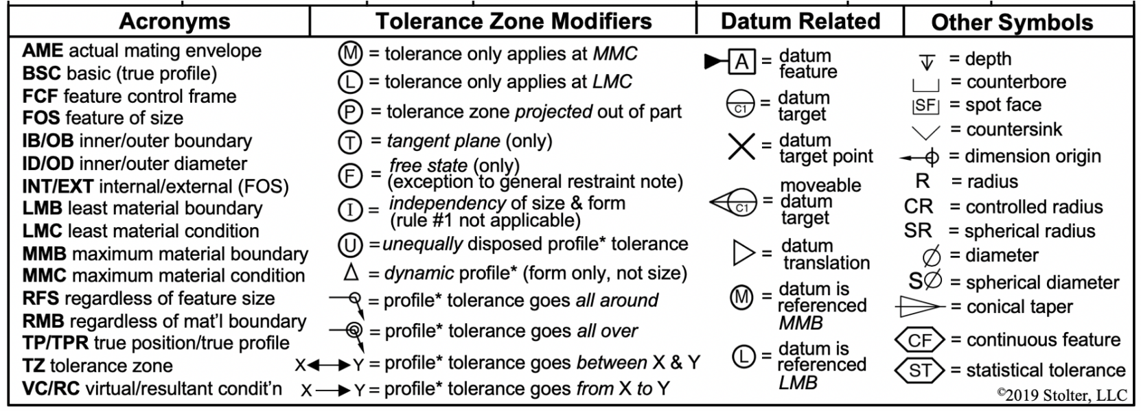
5.3 Geometric dimensioning and tolerancing (GD&T)
5. Advance
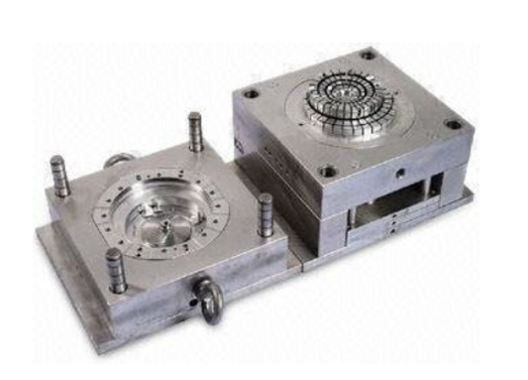
5.1 Mould Types
The creation of a well-balanced feed system requires careful consideration of the following elements- Single-cavity, multi-cavity, or family mold
- Cavity layout
- Location of the Sprue
- Runner system layout
- Shape of the Sprue, runners, and gates.
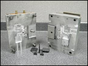
A. Single-cavity, multi-cavity, or family mold
- Single‐cavity molds are frequently used for limited production runs or when the part is very large, so that the size requirement of the injection molding machine does not become excessive
- Multi‐cavity mold When more than one injected part, all the same, is made in the same mold
- Family mold Family injection molding produces a set of various shaped components that are molded at the same time and are manufactured from the same material.
- The family mold is a kind of multi-cavity mold where each cavity produces different parts of the same product. (like model airplanes, etc.)
B. Cavity Layouts
The cavities have to be arranged relatively to the central Sprue in such a way that the following conditions are met:- All cavities should be filled at the same time with melt of the same temperature.
- The flow length should be short to keep scrap to a minimum.
- The distance from one cavity to another has to be sufficiently large to provide space for cooling lines.
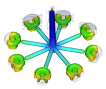
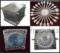
Circular Cavity layout
Series Cavity layout
Symmetrical Cavity layout
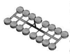
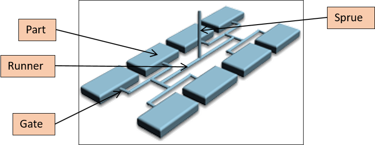
5.2 Feed system Design
Feed System Design Includes Design Of :- Gate : Section of the feed system that join the runner system to the part
- Runner : Sprue to the gates of each cavity in the mold
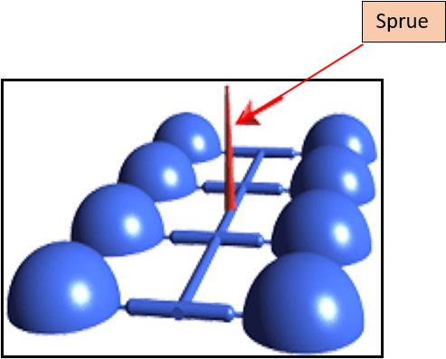
- Sprue : Extension of the injection nozzle into the mold
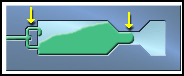
- The Sprue is the extension of the injection nozzle into the mold.
- In a single cavity mold with a single injection location, the Sprue can meet at the cavity wall.
- The Sprue is usually connected to a runner system as shown in the diagram.
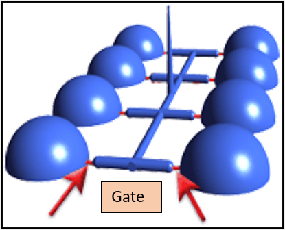
Gates connect the runner system to the cavity and the orifices through which the melt enters the mold.
- Considerations to be followed while designing the gates:
- The final appearance of the molded part: For parts where appearance is important, the gates should be narrow to prevent large blemishes on the surface of the part
- Removal of the gate: A smaller opening will make gate removal easier.
- Complexity of the cavity
- The material used
- The volume of the material injected into the mold
A runner is a machined groove located between the Sprue Bushing and the gate to provide a passage for the material to flow.
- The design of the runners is important to ensure even filling of the cavities.
- The design of the runners is dependent on whether the mold is single cavity, multi-cavity, or part only.
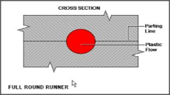
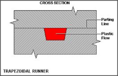
- There are many types of runner cross sectional shapes. Most common shapes are the Full Round, Half Round, and the Trapezoidal.
- Full Round Runner is the most efficient shape for reducing the cooling effect on the material as it flows in the runner.
- The Half Round runner is simply a runner system machined with a ball nose cutter into one plate of the mold.
- Trapezoidal Runners are very common in three plate molds. While not as efficient in chilling effect of a full round runner, the ease of cutting the runner shape, and the elimination of the need to mate two runner plates together, makes the trapezoidal runner a good second choice of runner shape.
5.3 Types of gates- manually trimmed gates
-
Direct Sprue Gate :
- commonly used for single-cavity molds, where the sprue feeds material directly and rapidly into the cavity with minimum pressure drop.
-
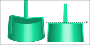
Disc or Diaphragm Gate:
- A disc gate is often used for gating cylindrical or round parts that have an open inside diameter.
-
Fan Gate:
- A fan gate is a wide edge gate with variable thickness, which permits rapid filling of large parts or fragile mold sections through a large entry area.
-
Edge or Standard Gate:
- An edge gate is located on the parting line of the mold.
-
Overlap Gate:
- It is similar to an edge gate but a portion of the gate overlaps the part.
-
Film or Flash Gate:
- A film gate consists of a straight runner and a gate land across the entire width of the cavity or a portion of the cavity.
-
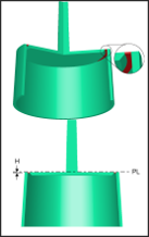
Ring Gate:
- With a ring gate, the material flows freely around the core before it moves down as a uniform tube-like extrusion to fill the mold.
-
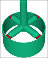
Spoke or Spider Gate:
- It is also called a four-point gate or cross gate. This gate is used for tube-shaped parts and offers easy gate removal and material savings.
-
Tab Gate:
- It is typically employed for parts that require low shear stresses, such as optical parts.
5.4 Automatically Trimmed Gates
-
Hot Runner or Hot Probe Gate:
- Generally used to deliver hot material through heated runners directly into the cavity to produce runner less moldings.
-
Valve Gate:
- It adds a valve pin to the hot runner gate.
- Valve gates have a larger gate diameter and they can be opened and closed as needed. This smooths over the gate scar.
-
Submarine, Tunnel or Chisel gate:
- Used in two-plate mold construction. An angled, tapered tunnel is machined from the end of the runner to the cavity, just below the parting line.
-
Pin Gate:
- Used in a three-plate mold design, where the runner system is on a secondary mold parting line and the part cavity is in the primary parting line.
5.5 Best gate location
Ideally, gates should be placed in the deepest cross-section to provide the best flow and minimize voids and sinking.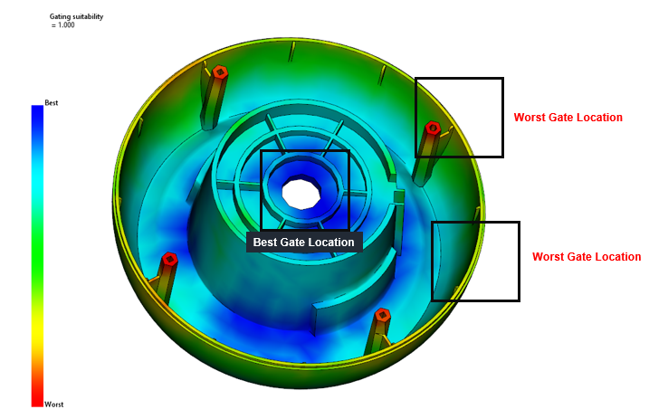
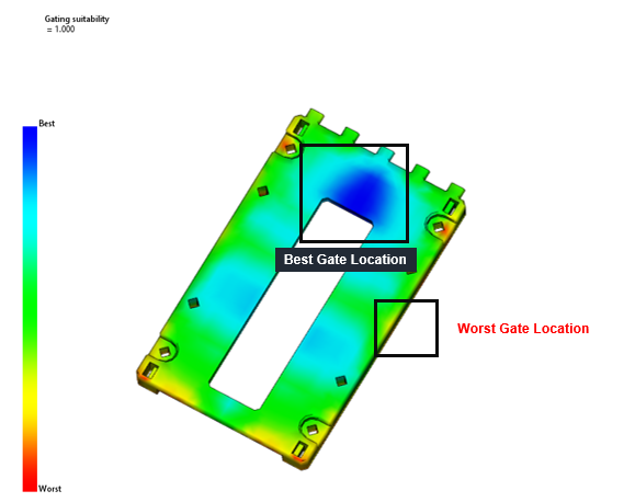
- Avoid obstructions: Place gates away from severe obstructions like ejectors, pins.
- Seek strength: Place gates at a thick section of the part to optimize part packing.
- Consider function and aesthetics: position them where they won’t affect how the finished part looks or functions.
- Design for de-gating: Your gate location can affect how easily a part can be de-gated from the runner
- Roundness and flatness : If roundness or flatness is a critical requirement, tread carefully on one side.
- Consider two gates : With some parts, you may have to have two gates to ensure proper filling
- Minimize flow marks : The longer the flow path in a part, the greater the chance of flow marks.
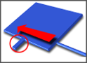
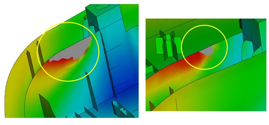
5.6 Plastic Defects-Flow Hesitation
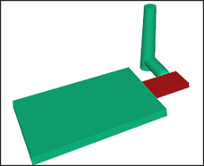
- Hesitation which occurs when the melt flow slows down or stops along a particular flow path, can lead to asymmetrical and unpredictable flow patterns
- When the melt entering a cavity is filling a thin section and a thick section, it tends to fill the thick section first because this route is less resistant to flow. This can result in the melt in the thin section stopping or slowing significantly.
- The melt cools more rapidly as it starts to slow down so the viscosity increases. In turn, this higher viscosity inhibits flow further.
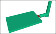
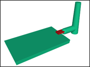
- In the following diagram, the rib circled in red offers a higher resistance to flow because it is much thinner than the rest of the part
- Move the polymer injection location away from the area of hesitation
- Move the polymer injection location to a place that will cause greater pressure to be applied where the hesitation occurred.
- Increase the wall thickness where the hesitation occurred,
- Use a less viscous material
- Inject more quickly to reduce the potential of hesitation time.
- Increase the melt temp so that it flows into the thin area more readily.
5.7 Plastic Defects-Short Shot
Short Shot :- A short shot is the incomplete filling of a mold cavity which results in the production of an incomplete part.
- If a part short shots, the plastic does not fill the cavity.
- The flow freezes off before the flow paths have completely filled.
- Flow restrictions. Due to channels freezing or inadequate runner design.
- Hesitation and long or complex flow paths.
- Inadequate venting. Back pressure due to unvented air traps can cause a short shot.
- Low melt and/or mold temperatures.
- Insufficient material entering the cavity.
- Machine defects. Including an empty hopper, blocked feed throat.
- Avoid flow hesitation.
- Eliminate air traps
- Increase mold and melt temperature
- Increase ram speed:
- Change the part geometry. Balance flow paths,or reduce the complexity of a flow path.
- Use a different material. Select a less viscous material (higher melt flow rate).
- Increase the maximum injection pressure for this part.
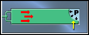
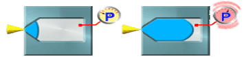
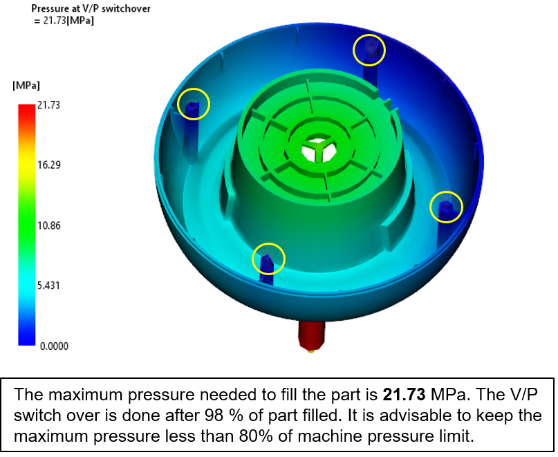
5.8 Filling Process- VP Switchover
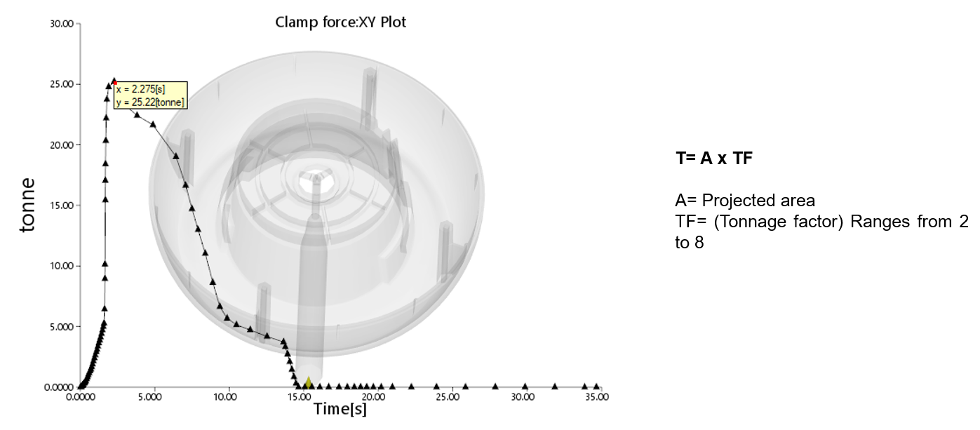
VP Switchover:- It is pressure distribution through the flow path inside the mold at the switchover point from velocity to pressure control.
- During the filling stage, large variations in the pressure distribution, indicated by closely-spaced contours, should be avoided.
5.9 Clamping force XY-plot
5.10 Plastic Defects-Sink Mark
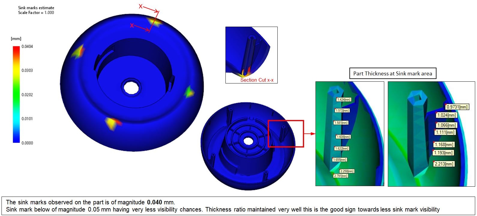
- Sink marks appear as depressions on the surface of a molded part.
- These depressions are typically very small;
- The visibility of sink marks is a function of the color of the part as well as its surface texture so depth is only one criterion.
- Although sink marks do not affect part strength or function
- Thermal contraction (shrinkage) during cooling: After the material on the outside has cooled and solidified, the core material starts to cool. Its shrinkage pulls the surface of the main wall inward, causing a sink mark.
- Localized geometric features: Sink marks typically occur in moldings with thicker sections, or at locations opposite from ribs,
- High volumetric shrinkage.
- Short packing or cooling time.
- High melt and/or mold temperatures.
- Optimize packing profile. As sink marks occur during packing,
- Change the part geometry.
- Reduce volumetric shrinkage.
- Relocate gates to problem areas..
- Optimize the runner system design.
- Use a different material
5.11 Plastic Defects-Weld lines
- When a weld lines forms, the thin frozen layers at the front of each flow path meet,
- The animation shows plastic filling a cavity. The weld occurs where two flow fronts meet, and the polymer molecules are misaligned.
- It is the sharp difference in molecular orientation at the weld which causes the significant decrease in strength at this point.
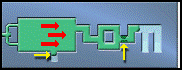
5.12 Plastic Defects-Meld lines
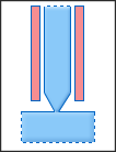
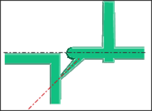
Meld lines :- A meld line occurs when two flow fronts blend together at an oblique angle. The orientation of the plastic molecules is therefore more uniform than the orientation after a weld line has formed.
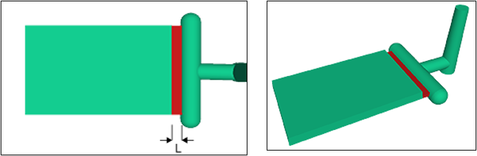
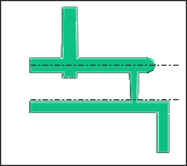
- The following diagram shows the length of a part where a meld line forms. The red arrows show the direction of plastic flow. The white lines represent the orientation of the polymer molecules after the meld line has formed.
- Meld lines are normally stronger than welds and are often much less visible.
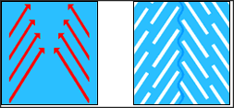
- It is determined by the angle at which the converging flow fronts meet.
- In the right side diagram, the converging flow fronts (indicated by black arrows) meet. If the angle, is greater than 135° a meld line will form. If is less than 135° a weld will form.

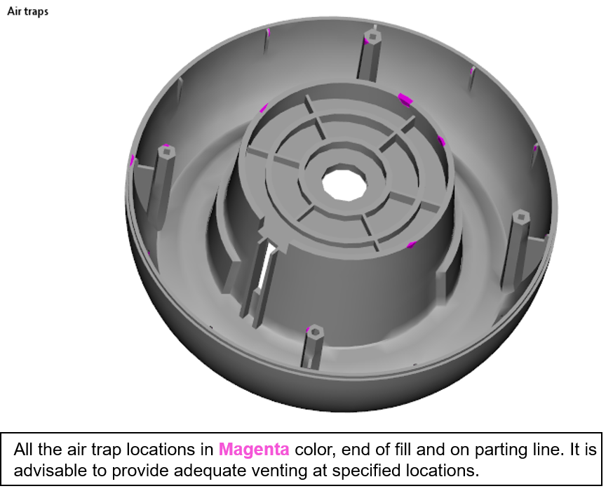
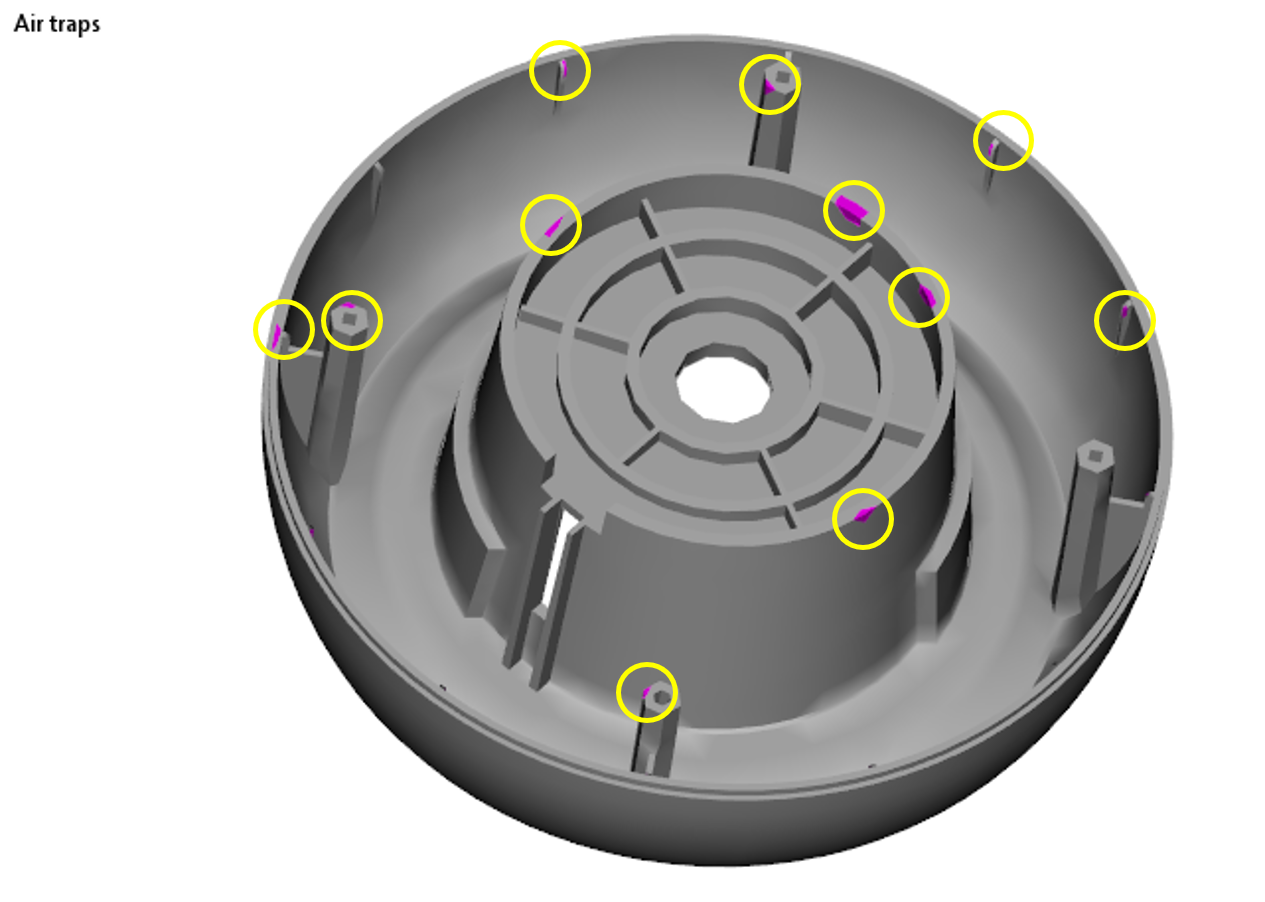
5.13 Plastic Defects-Air traps
Airtraps :- Airtrap is the air that is caught inside the mold cavity.
- It becomes trapped by converging polymer melt fronts or because it failed to escape from mold vents.
- It results in voids and bubbles inside the molded parts,short shot or surface defects.
5.14 Warpage
Plastic warpage or plastic warping is usually a dimensional distortion that occurs in a molded product after it is ejected from the mold. Warping in injection molding is actually a deviation which is caused by the unintentional bending and twisting of the plastic part at the end of the injection molding process.
Causes of Warpage :
-
Differential Cooling
- Differential Shrinkage
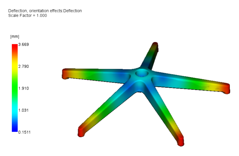
- Orientation effects
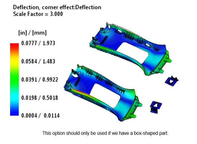
- Corner effects
- Differential Shrinkage